Cutting Offset Calculator
Input Parameters
Offset Results
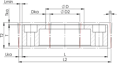
| Outer Kerf Offset (Lₖₐ): | mm |
| Inner Kerf Offset (Dₖₐ): | mm |
Calculation Steps
Technical Diagram
Clearance Hole Specifications
(Based on DIN EN 20273/ISO 273 Standards)
| Metric Thread | Medium | Coarse |
|---|---|---|
| M5 | 5.5 | 5.8 |
| M6 | 6.6 | 7 |
| M8 | 9 | 10 |
| M10 | 11 | 12 |
| M12 | 13.5 | 14.5 |
| M14 | 15.5 | 16.5 |
| M16 | 17.5 | 18.5 |
| M18 | 20 | 21 |
| M20 | 22 | 24 |
| M24 | 26 | 28 |
| M27 | 30 | 32 |
| M30 | 33 | 35 |
| M36 | 39 | 42 |
Sizes are color-coded based on suitability for the selected plate thickness. Always verify dimensions before finalizing your DXF file.
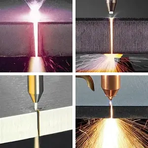
Determine offset values for DXF files and raw dimensions in CAD models. This tool calculates kerf compensation based on plate thickness and machining parameters to ensure final dimensions align with design specifications after laser, plasma, or CNC machining.
Sample Process