Engineering Data Sheets
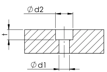
Counterbore Dimensions for ISO 4762 Screws
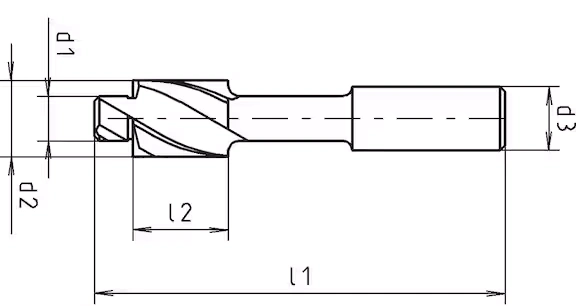
(Counterborer with straight shank and fixed pilot - DIN 373)- d
- Metric Thread
- d1
- Clearance Hole Diameter (mm)
- d2
- Counterbore Diameter (mm)
- t
- Counterbore Depth (mm)
| d | d1 | d2 | t |
|---|---|---|---|
| M3 | 3.4 (3.2) | 6 | 3.3 |
| M4 | 4.5 (4.3) | 8 | 4.4 |
| M5 | 5.5 (5.3) | 10 | 5.4 |
| M6 | 6.6 (6.4) | 11 | 6.4 |
| M8 | 9 (8.4) | 15 | 8.4 |
| M10 | 11 (10.5) | 18 | 10.4 |
| M12 | 13.5 (13) | 20 | 12.4 |
| M14 | 15.5 (15) | 24 | 14.4 |
| M16 | 17.5 (17) | 26 | 16.4 |
| M18 | 20 (19) | 30 | 18.5 |
| M20 | 22 (22) | 33 | 20.5 |
| M24 | 26 (25) | 40 | 24.6 |
| M27 | 30 (28) | 45 | 27.6 |
| M30 | 33 (31) | 50 | 30.6 |
| M36 | 39 (37) | 60 | 36.7 |
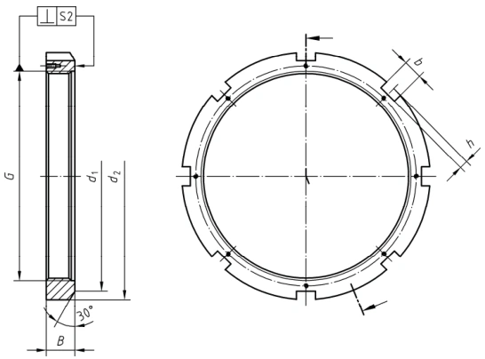
DIN 981 KM Lock Nut Dimensions
- KM
- Lock Nut Code
- G
- Metric Thread Size
- d2
- Outer Diameter (mm)
- B
- Height (mm)
| KM | G | d2 | B |
|---|---|---|---|
| KM0 | M10 x 0.75 | 18 | 4 |
| KM1 | M12 x 1 | 22 | 4 |
| KM2 | M15 x 1 | 25 | 5 |
| KM3 | M17 x 1 | 28 | 5 |
| KM4 | M20 x 1 | 32 | 6 |
| KM5 | M25 x 1.5 | 38 | 7 |
| KM6 | M30 x 1.5 | 45 | 7 |
| KM7 | M35 x 1.5 | 52 | 8 |
| KM8 | M40 x 1.5 | 58 | 9 |
| KM9 | M45 x 1.5 | 65 | 10 |
| KM10 | M50 x 1.5 | 70 | 11 |
| KM11 | M55 x 2 | 75 | 11 |
| KM12 | M60 x 2 | 80 | 11 |
| KM13 | M65 x 2 | 85 | 12 |
| KM14 | M70 x 2 | 92 | 12 |
| KM15 | M75 x 2 | 98 | 13 |
| KM16 | M80 x 2 | 105 | 15 |
| KM17 | M85 x 2 | 110 | 16 |
| KM18 | M90 x 2 | 120 | 16 |
| KM19 | M95 x 2 | 125 | 17 |
| KM20 | M100 x 2 | 130 | 18 |
| KM21 | M105 x 2 | 140 | 18 |
| KM22 | M110 x 2 | 145 | 19 |
| KM23 | M115 x 2 | 150 | 19 |
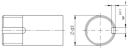
DIN 5406 MB Lock Washer Mounting Dimensions
- MB
- Lock Washer Code
- d1
- Inner Diameter (mm)
- w
- Width H11 (mm)
- t
- Thickness (mm)
- s
- Slot Width (mm)
- d2
- Outer Diameter (mm)
| MB | d1 | w H11 | t | s | d2 |
|---|---|---|---|---|---|
| MB0 | 10 | 4 | 2 | 1 | 21 |
| MB1 | 12 | 4 | 2 | 1 | 25 |
| MB2 | 15 | 5 | 2 | 1 | 28 |
| MB3 | 17 | 5 | 2 | 1 | 32 |
| MB4 | 20 | 5 | 2 | 1 | 36 |
| MB5 | 25 | 6 | 3 | 1.2 | 42 |
| MB6 | 30 | 6 | 4 | 1.2 | 49 |
| MB7 | 35 | 7 | 4 | 1.2 | 57 |
| MB8 | 40 | 7 | 4 | 1.2 | 62 |
| MB9 | 45 | 7 | 4 | 1.2 | 69 |
| MB10 | 50 | 7 | 4 | 1.2 | 74 |
| MB11 | 55 | 9 | 4 | 1.5 | 81 |
| MB12 | 60 | 9 | 4 | 1.5 | 86 |
| MB13 | 65 | 9 | 4 | 1.5 | 92 |
| MB14 | 70 | 9 | 5 | 1.5 | 98 |
| MB15 | 75 | 9 | 5 | 1.5 | 104 |
| MB16 | 80 | 11 | 5 | 1.7 | 112 |
| MB17 | 85 | 11 | 5 | 1.7 | 119 |
| MB18 | 90 | 11 | 5 | 1.7 | 126 |
| MB19 | 95 | 11 | 5 | 1.7 | 133 |
| MB20 | 100 | 14 | 6 | 1.7 | 142 |
| MB21 | 105 | 14 | 6 | 1.7 | 145 |
| MB22 | 110 | 14 | 6 | 1.7 | 154 |
| MB23 | 115 | 14 | 6 | 2 | 159 |
DIN 71412 Grease Nipple Types
| Type and Size | Description as per Standard |
|---|---|
| DIN 71412 A M5x0.8 | Straight (180°) Conical Head |
| DIN 71412 A M6x1 | Straight (180°) Conical Head |
| DIN 71412 A M8x1 | Straight (180°) Conical Head |
| DIN 71412 A M10x1 | Straight (180°) Conical Head |
| DIN 71412 A R(G) 1/8" | Straight (180°) Conical Head |
| DIN 71412 A R(G) 1/4" | Straight (180°) Conical Head |
| DIN 71412 B M6x1 | 45° Angled Conical Head |
| DIN 71412 B M8x1 | 45° Angled Conical Head |
| DIN 71412 B M10x1 | 45° Angled Conical Head |
| DIN 71412 B R(G) 1/8" | 45° Angled Conical Head |
| DIN 71412 C M6x1 | 90° Angled Conical Head |
| DIN 71412 C M8x1 | 90° Angled Conical Head |
| DIN 71412 C M10x1 | 90° Angled Conical Head |
| DIN 71412 C R(G) 1/8" | 90° Angled Conical Head |
| DIN 71412 C R(G) 1/4" | 90° Angled Conical Head |
Motor Rating vs. Shaft Size (1400 - 1500 RPM)
| Motor (kW) | Motor (HP) | Shaft Size (mm) | Keyway (mm) |
|---|---|---|---|
| 1.1 | 1.5 | 24 | 8 |
| 1.5 | 2 | 24 | 8 |
| 2.2 | 3 | 28 | 8 |
| 3.7 | 5 | 28 | 8 |
| 5.5 | 7.5 | 38 | 10 |
| 7.5 | 10 | 38 | 10 |
| 9.3 | 12.5 | 42 | 12 |
| 11 | 15 | 42 | 12 |
| 15 | 20 | 42 | 12 |
| 18.5 | 25 | 48 | 14 |
| 22 | 30 | 48 | 14 |
| 30 | 40 | 55 | 16 |
| 37 | 50 | 60 | 18 |
| 45 | 60 | 60 | 18 |
| 55 | 75 | 65 | 18 |
| 75 | 100 | 75 | 22 |
See also 📚
Related standards and tools you might find useful:
A Compact Reference for Everyday Parts
Design and purchasing departments reach for the same small set of dimension tables every day: the counterbore for a socket head cap screw, a KM lock nut for a bearing, a motor shaft diameter for a coupling. This page collects those tables in one place so you can read the values directly from the sheet instead of hunting through separate catalogues. Every dataset is linked to its governing standard - ISO 4762, DIN 981, DIN 5406, DIN 71412, and the IEC motor-shaft convention.
How to Read the Dimension Tables
Each table has a legend that defines the dimension symbols used, for example d₁ for the clearance hole, d₂ for the counterbore diameter, and t for the depth. To find a value, locate your metric thread size (such as M8 for a cap screw or M40 x 1.5 for a KM8 nut) in the first column and read the matching dimensions across the row. Lock-nut and lock-washer codes such as KM0 or MB23 are matched by their thread size in the second column.
Consistency Across Standards
The tables reflect the same standards mentioned elsewhere on Kod5, so a KM lock nut here matches the superfine-pitch thread rows in the metric thread pitch guide, and the motor shaft/keyway table aligns with the DIN 6885 keyway references. That consistency lets you move from sizing a fastener to ordering its mating hardware without converting units or re-checking catalogs.
Frequently Asked Questions
What are the counterbore dimensions for an M8 socket head cap screw (ISO 4762)?
For an M8 screw, the standard clearance hole (d1) is 9 mm, the counterbore diameter (d2) is 15 mm, and the counterbore depth (t) is 8.4 mm.
What are the dimensions for a KM8 lock nut (DIN 981)?
A DIN 981 KM8 lock nut has a metric thread size of M40 x 1.5, an outer diameter (d2) of 58 mm, and a height (h) of 9 mm.
What size shaft is on a 7.5 kW motor?
A standard 7.5 kW motor (10 HP) running at 1400-1500 RPM typically has a shaft size of 38 mm with a 10 mm keyway.