Spur Gear Dimensions
Inputs:
Results
| Parameter | Gear 1 (mm) | Gear 2 (mm) |
|---|---|---|
| Addendum Dia. (da) | ||
| Pitch Dia. (d) | ||
| Base Circle Dia. (db) | ||
| Dedendum Dia. (df) | ||
| Center Distance (C) | ||
Calculation Details
Frequently Asked Questions
What does Spur Gear Dimensions do?
Spur gear calculator: compute module, pitch diameter, addendum, dedendum and tooth geometry from gear parameters.
How do I use Spur Gear Dimensions?
Enter the number of teeth, module (m), and pressure angle. The calculator returns pitch diameter, base circle, addendum, dedendum, outside diameter, and tooth thickness.
Is Spur Gear Dimensions free to use?
Yes. This spur gear dimension calculator is free, fully browser-based, and requires no installation or login.
Spur Gear Geometry Explained
A spur gear transmits power between parallel shafts using straight-cut teeth. Its geometry is defined by the module (m) — the ratio of pitch diameter to number of teeth — and the number of teeth (z). All other dimensions are derived from these two values using standard formulas, so a single pair of inputs lets you generate the complete tooth profile for machining, inspection, or CAD modelling.
The module is a standardized value in millimetres, and gear cutters are manufactured for each module size. Common modules range from fine instrument gears of 0.2 mm up to heavy industrial gears of 60 mm. Choosing the right module depends on the torque to be transmitted and the available space; a larger module produces stronger, thicker teeth.
Key Formulas Used
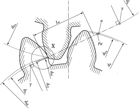
- Pitch diameter: d = m × z — the reference circle where gear tooth profiles are designed.
- Addendum circle: da = d + 2m — the outer tip diameter of the gear.
- Dedendum circle: df = d − 2.5m — the root circle between the teeth.
- Base circle: db = d × cos(20°) — the circle from which the involute tooth curve is generated.
- Center distance: C = m × (z1 + z2) / 2 — the spacing between the two shaft centres.
- Tooth thickness: t = π × m / 2 — measured along the pitch circle.
What Is the Pressure Angle?
This calculator assumes the standard 20° pressure angle per ISO 53, used on virtually all modern involute spur gears. The pressure angle controls the shape of the tooth flank and affects load capacity, backlash, and the minimum number of teeth before undercut occurs. At 20°, gears should generally have at least 17–18 teeth to avoid weakened undercut roots; the tool enforces 18 teeth as the practical minimum.
How to Read the Results
Enter the module and the tooth counts of the gear pair. The table returns pitch, addendum, base, and dedendum diameters for both gears plus the center distance — everything needed to dimension a drawing or select a blank for turning. The Calculation Details box writes out every step of the math so you can verify the values manually or document them in a report.